


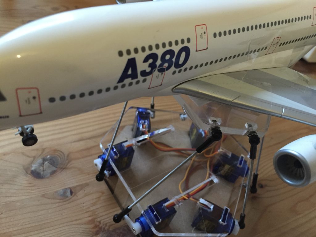
Hier mal ein erster Test einer 6DOF Stewart Plattform auf Servo und arduino-basis in Verbindung mit SIMTOOLS.
/*
//********************************************************************************************
// RC Model Servo
// Original code By EAOROBBIE (Robert Lindsay)
// Completely mangled by aarondc
// For free use for Sim Tool Motion Software
// Changed by SIM-PC.de for 6DOF
//********************************************************************************************
#include
//#define DEBUG 1               // comment out this line to remove debuggin Serial.print lines
const int kActuatorCount = 6;   // how many Actuators we are handling

// the letters ("names") sent from Sim Tools to identify each actuator
// NB: the order of the letters here determines the order of the remaining constants kPins and kActuatorScale
const char kActuatorName[kActuatorCount] = { 'A', 'B', 'C', 'D', 'E', 'F' };
const int kPins[kActuatorCount] = {2, 3, 4, 5, 6, 7};
const int kActuatorScale[kActuatorCount][6] = { { 0, 179 } ,    // 1 Actuator scaling
                                                { 0, 179 } ,    // 2 Actuator scaling
                                                { 0, 179 } ,    // 3 Actuator scaling
                                                { 0, 179 } ,    // 4 Actuator scaling
                                                { 0, 179 } ,    // 5 Actuator scaling
                                                { 0, 179 }      // 6 Actuator scaling
                                               };
const char kEOL = '~';                              // End of Line - the delimiter for our acutator values
const int kMaxCharCount = 3;                        // some insurance...
Servo actuatorSet[kActuatorCount];                  // our array of Actuators
int actuatorPosition[kActuatorCount] = {90,90,90,98,90,90};    // current Actuator positions, initialised to 90
int currentActuator;                                // keep track of the current Actuator being read in from serial port
int valueCharCount = 0;                             // how many value characters have we read (must be less than kMaxCharCount!!

// set up some states for our state machine
// psReadActuator = next character from serial port tells us the Actuator
// psReadValue = next 3 characters from serial port tells us the value
enum TPortState { psReadActuator, psReadValue };
TPortState currentState = psReadActuator;

void setup()
{
    // attach the Actuators to the pins
    for (int i = 0; i < kActuatorCount; i++)
        actuatorSet[i].attach(kPins[i]);

    // initialise actuator position
    for (int i = 0; i < kActuatorCount; i++) updateActuator(i); Serial.begin(38400); // opens serial port at a baud rate of 9600 } void loop() { } // this code only runs when we have serial data available. ie (Serial.available() > 0).
void serialEvent() {
    char tmpChar;
    int tmpValue;

    while (Serial.available()) {
        // if we're waiting for a Actuator name, grab it here
        if (currentState == psReadActuator) {
            tmpChar = Serial.read();
            // look for our actuator in the array of actuator names we set up
#ifdef DEBUG
Serial.print("read in ");
Serial.println(tmpChar);
#endif
            for (int i = 0; i < kActuatorCount; i++) {
                if (tmpChar == kActuatorName[i]) {
#ifdef DEBUG
Serial.print("which is actuator ");
Serial.println(i);
#endif
                    currentActuator = i;                        // remember which actuator we found
                    currentState = psReadValue;                 // start looking for the Actuator position
                    actuatorPosition[currentActuator] = 0;      // initialise the new position
                    valueCharCount = 0;                         // initialise number of value chars read in
                    break;
                }
            }
        }

        // if we're ready to read in the current Actuator's position data
        if (currentState == psReadValue) {
            while ((valueCharCount < kMaxCharCount) && Serial.available()) {
                tmpValue = Serial.read();
                if (tmpValue != kEOL) {
                    tmpValue = tmpValue - 48;
                    if ((tmpValue < 0) || (tmpValue > 9)) tmpValue = 0;
                    actuatorPosition[currentActuator] = actuatorPosition[currentActuator] * 10 + tmpValue;
                    valueCharCount++;
                }
                else break;
            }

            // if we've read the value delimiter, update the Actuator and start looking for the next Actuator name
            if (tmpValue == kEOL || valueCharCount == kMaxCharCount) {
#ifdef DEBUG
Serial.print("read in ");
Serial.println(actuatorPosition[currentActuator]);
#endif
                // scale the new position so the value is between 0 and 179
                actuatorPosition[currentActuator] = map(actuatorPosition[currentActuator], 0, 255, kActuatorScale[currentActuator][0], kActuatorScale[currentActuator][1]);
#ifdef DEBUG
Serial.print("scaled to ");
Serial.println(actuatorPosition[currentActuator]);
#endif
                updateActuator(currentActuator);
                currentState = psReadActuator;
            }
        }
    }
}


// write the current Actuator position to the passed in Actuator
void updateActuator(int thisActuator) {
    actuatorSet[thisActuator].write(actuatorPosition[thisActuator]);
}
Da doch einige Anfragen zur Ansteuerung eines TM1638 mit dem rcc gekommen sind, habe ich hier mal ein einfaches Beispiel für eine Drehzahlanzeige gemacht.
//https://github.com/rjbatista/tm1638-library
#include
// define a module on data (DIO) pin 8, clock (CLK) pin 9
// and strobe (STB0)pin 10
TM1638 module(8, 9, 10);

String ver = "2.0.0.0";

const int nChar = 30; // size of char
String inString = ""; // a string to hold incoming data
boolean stringComplete = false; // whether the string is complete

int vRpm;

void setup()
{
Serial.begin(38400);
}

void readdata() {
if (stringComplete) {
if (inString.substring(0, 2) == "RR") {
vRpm = inString.substring(2, 6).toInt();
module.setDisplayToDecNumber(vRpm * 10,0,false);
}
inString = "";
stringComplete = false;
}
}

void serialReadEvent() {
while (Serial.available()) {
char inChar = (char)Serial.read();
inString += inChar;
if (inChar == ';') {
stringComplete = true;
}
}
}

void loop() {
serialReadEvent();
readdata();
}
Im moment arbeite ich an eine stark erweiterte Version vom
rcc (real cockpit connector) als kompletter Gamedash zur Ansteuerung von unterschiedlichster Hardware.
Ein einfaches Möglichkeit um z.b. eine Drehzahlanzeige in einem Cockpit zu steuern wäre die Kontrolle mit einem Servo.
/*
    This is a servo sample for rcc with rpm
    http://www.arduino.cc/en/Tutorial/Sweep
*/
#include Servo myservo;          // create servo object to control a servo,
                                 //twelve servo objects can be created on most boards

String ver = "2.0.0.3";

const int servPin = 9;           // Servo Pin
const int nChar = 30;            // size of char
String inString = "";            // a string to hold incoming data
boolean stringComplete = false;  // whether the string is complete


void setup() {
  myservo.attach(servPin);       // attaches the servo to the servo object
  inString.reserve(nChar);
  Serial.begin(38400);
}

void readdata() {
  if (stringComplete) {
    if (inString.substring(0, 2) == "RR") {
      int vRpm = inString.substring(2, 6).toInt();
      int pos = map(vRpm, 0, 800, 255, 0);
      myservo.write(pos);
    }
    inString = "";
    stringComplete = false;
  }
}

void serialReadEvent() {
  while (Serial.available()) {
    char inChar = (char)Serial.read();
    inString += inChar;
    if (inChar == ';') {
      stringComplete = true;
    }
  }
}

void loop() {
  serialReadEvent();
  readdata();
}
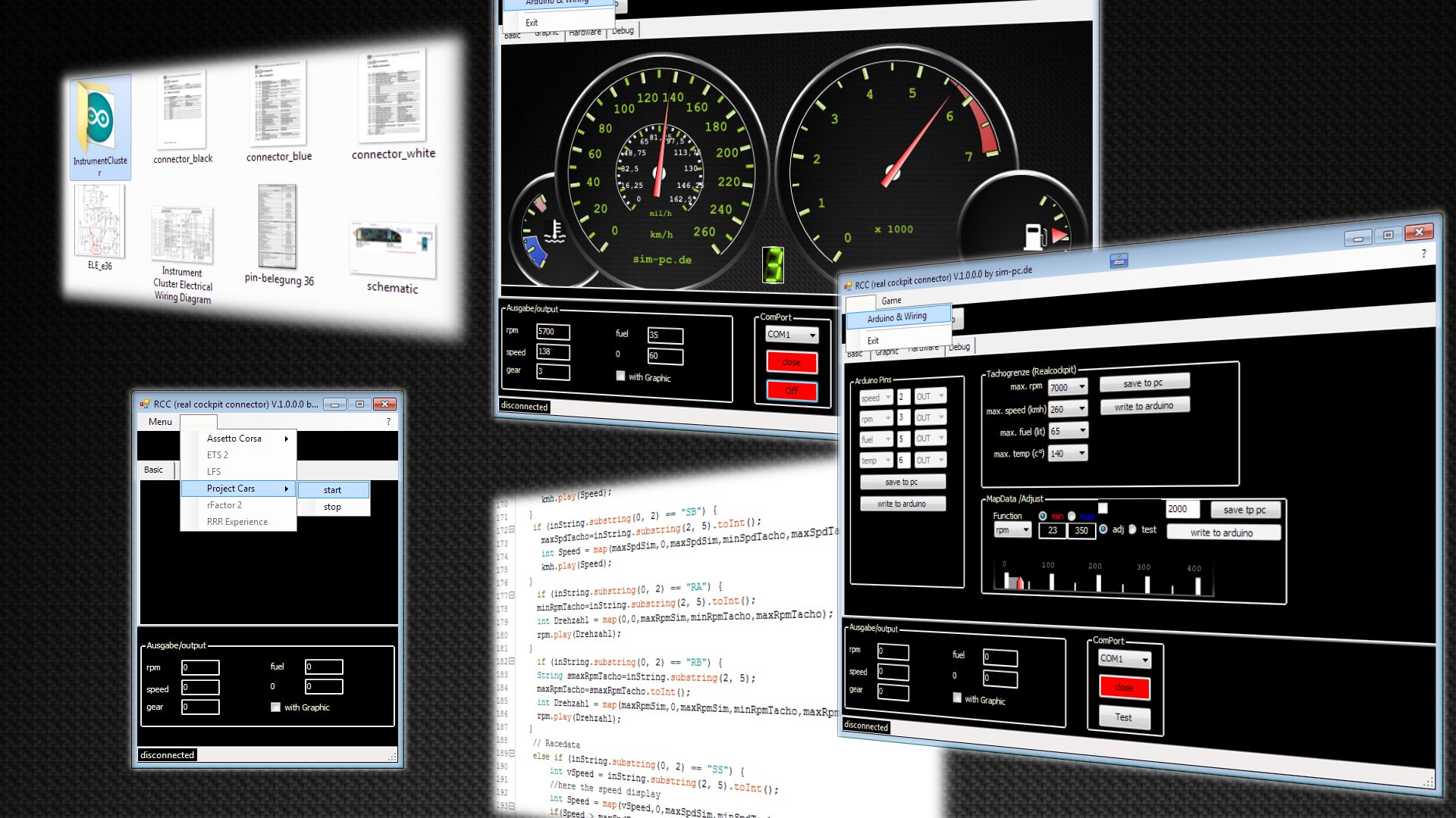
Da ich nicht unbedingt der Handbuchschreiber bin, habe ich mal ein einfaches kurzes Tutorial zum „rcc“ als Video hochgeladen.
Das Programm kann wahrscheinlich ab dem 23.01.2016 hier geladen werden.
Falls probleme mit dem Video sind, hier der Youtubelink: https://youtu.be/WWnBEGLMBAk
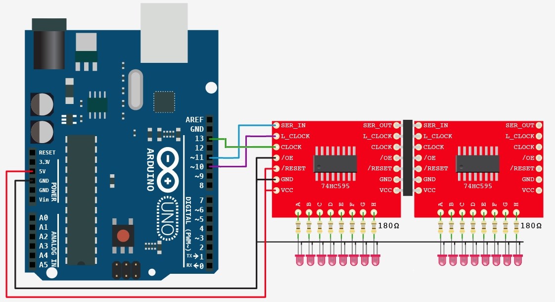
Mit 3 Kabel, Anzahl x Led’s, am Arduino ansteuern.
das Shift Register Breakout – 74HC595 mit Hardware SPI
Demo (8 x Led & 1 x 7 segment) mit 2 x 74HC595
#include <SPI.h>
//                      Mega2560  74HC595  ARDUINO SPI
int dataPin = 11;       // 51     SER    =   MOSI
int latchPin = 10;      // 53     RCLK   =   SS
int clockPin = 13;      // 52     SRCLK  =   SCLK

int N1[9] = {63,6,91,79,102,109,124,7,127};
int N2[9] = {0,1,3,7,15,31,63,127,255};

void setup()
{
  pinMode(latchPin, OUTPUT);
  digitalWrite(latchPin, LOW);

  //Setup SPI
 SPI.setBitOrder(MSBFIRST);
 SPI.begin();
}

void loop() {
   for (byte i=0; i < 9; i++)
    {
      writeOutput(N1[i], N2[i]);
      delay(500);
    }
}

void writeOutput(int b1, int b2)
{
    digitalWrite(latchPin, HIGH);  // Pull latch LOW to send data
    SPI.transfer(b1);
    SPI.transfer(b2);
    digitalWrite(latchPin, LOW);   // Lower the latch to apply the changes
}
Alle funktionen des Tacho, Ganganzeige, eine 8 stellige konfigurierbare LED-Anzeige für Rpm
#include
#include
char kind_of_data;
// shiftpoint #############
int ShiftPoint  = 0;
int RpmSimTools = 6500;  // Schaltpunkt vorbelegen
int LimitRange  = 0;
int UnderShiftPoint;
int OverShiftPoint;
int OverShift;
int UnderShift;
int ButtonState;
int LastButtonState = LOW;
long lastDebounceTime = 0;
long debounceDelay    = 5;
//LED rpm
int rpmLED = 0;
// 7segment Common Cathode
int Gear;
int GearLight = 0;
int N1[9] = {63,6,91,79,102,109,124,7,80};  // 0 1 2 3 4 5 6 7 r
//arduino pins
int prpm = 2;
int pkmh = 3;
int ful  = 5;   // pwm
int tmp  = 6;   // pwm
int capture_button = 4;  //shift point capture button
int analog_adj_pot = 0;  // adjusting poti
//arduino spi pins nach 74HC595 (Shiftregister)
int latchpin = 10;   // blaues kabel >> RCLK   (Register clock)
int clockpin = 13;   // grünes kabel >> SRCLK  (Shift register clock)
int datapin  = 11;   // gelbes kabel >> SER    (Serial data input)
// Tone
Tone kmh;
Tone rpm;

void setup(){
  pinMode(latchpin, OUTPUT);
  pinMode(ful, OUTPUT);
  pinMode(tmp, OUTPUT);
  pinMode(capture_button,INPUT);

  digitalWrite(latchpin, LOW);

  //Setup SPI
  SPI.setBitOrder(MSBFIRST);
  SPI.begin();

  //Setup TONE
  kmh.begin(pkmh);
  rpm.begin(prpm);

  Serial.begin(115200);
  // Vorbelegung auf 50°c
  analogWrite(tmp,85);
  // Vorbelegung auf 30 Ltr.
  analogWrite(ful,95);
}

void CheckButtonPress() {   // shiftlight
  int reading = digitalRead(capture_button);
  if (reading != LastButtonState){
    lastDebounceTime = millis();
  }
  if ((millis() - lastDebounceTime) > debounceDelay) {
    if (reading != ButtonState){
      ButtonState = reading;
      if (ButtonState == HIGH){
        ShiftPoint = RpmSimTools;
      }
    }
  }
  LastButtonState = reading;
}

void CheckShiftLightAdj() {  // shiftlight nachjustieren
  LimitRange = analogRead(analog_adj_pot);
  int RpmAdjust = map(LimitRange, 1, 1023, 0, 2000);
  UnderShift = RpmAdjust;
  OverShift = RpmAdjust;
}

void SetLimits() {  // shiftlight
  UnderShiftPoint = ShiftPoint - UnderShift;
  OverShiftPoint = ShiftPoint + OverShift;
}

void ReadData(){
if(Serial.available() > 0) {
    kind_of_data = Serial.read();
    delay(1);
    int Data100 = Serial.read() - '0';
    delay(1);
    int Data10 = Serial.read()- '0';
    delay(1);
    int Data1 = Serial.read()- '0';

    //Daten anpassen: aus 1 wird 001, aus 10 wird 010 etc.
    while (Data1 < 0) {
      Data1 = Data10;
      Data10 = Data100;
      Data100 = 0;
    }

    int Data = 100*Data100 + 10*Data10 + Data1;
      //  Speed
      if (kind_of_data == 'S') {
      int Speed = map(Data,0,255,0,318);
      //  Gauge begrenzen
       if(Speed > 318) {
        Speed = 318;
        kmh.play(Speed);
       }
       else if((Speed <= 318) && (Speed >= 25)) {
        kmh.play(Speed);
       }
       else if(Speed < 25) {
        kmh.stop();
       }
      }

      // Drehzahl
      else if (kind_of_data == 'R') {
       RpmSimTools = Data*10;
       int Drehzahl = map(Data,0,700,0,350);

       if(Drehzahl > 350) {
        Drehzahl = 350;
       }
       if(Drehzahl < 025) {
        Drehzahl = 000;
       }
       rpm.play(Drehzahl);
     }

      // Gang
      else if (kind_of_data == 'G') {
       Gear = Data;

       if (Gear == 9) {   // rückwärts
        GearLight = N1[8];
       }
       if (Gear == 0) {   // neutral
        GearLight = N1[0];
       }
       if (Gear == 1) {   // 1 gang
        GearLight = N1[1];
       }
       if (Gear == 2) {   // 2 gang
        GearLight = N1[2];
       }
       if (Gear == 3) {   // 3 gang
        GearLight = N1[3];
       }
       if (Gear == 4) {   // 4 gang
        GearLight = N1[4];
       }
       if (Gear == 5) {   // 5 gang
        GearLight = N1[5];
       }
       if (Gear == 6) {   // 6 gang
        GearLight = N1[6];
       }
       if (Gear == 7) {   // 7 gang
        GearLight = N1[7];
       }
      }

      //Tankinhalt
      else if (kind_of_data == 'F') {
       int Tankinhalt = map(Data,0,65,13,155);

       if(Tankinhalt > 155) {
        Tankinhalt = 155;
       }
       if(Tankinhalt < 13) {
        Tankinhalt = 13;
       }
       analogWrite(ful,Tankinhalt);
     }

      //Temperatur
      else if (kind_of_data == 'T') {
       int Temperatur = map(Data,0,140,140,0);
       analogWrite(tmp,Temperatur);
      }

    DisplayLeds();
   }
}

void DisplayLeds(){

   if (RpmSimTools < UnderShiftPoint *0.25){
    rpmLED=0;
   }

   if (RpmSimTools >= UnderShiftPoint *0.25){
    rpmLED=1;
   }

   if (RpmSimTools >= UnderShiftPoint *0.5){
    rpmLED=3;
   }

   if (RpmSimTools >= UnderShiftPoint *0.75){
    rpmLED=7;
   }

   if (RpmSimTools >= UnderShiftPoint){
    rpmLED=15;
   }

   if (RpmSimTools >= ShiftPoint -500){
    rpmLED=31;
   }

   if (RpmSimTools >= ShiftPoint){
    rpmLED=63;
   }

   if (RpmSimTools >= OverShiftPoint -500){
    rpmLED=127;
   }

   if (RpmSimTools >= OverShiftPoint){
    rpmLED=255;
   }

  digitalWrite(latchpin, HIGH);
  SPI.transfer(GearLight);    // Ganganzeige
  SPI.transfer(rpmLED);       // LED's Drehzahl
  digitalWrite(latchpin, LOW);
}

void loop(){
  CheckButtonPress();
  CheckShiftLightAdj();
  SetLimits();
  ReadData();
}
Die passende GameDash konfiguration findet ihr >> hier <<